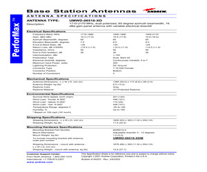
UMWD-06516-XD Description: 1710-2170 MHz, dual polarized, 65 degree azimuth beamwidth, 16 dBd gain panel antenna with variable electrical downtilt Electrical Specifications Frequency Band, MHz 1710-1880 1850-1990 1900-2170 Gain, dBd (dBi) 15.3 (17.5) 15.6 (17.8) 15.8 (18.0) Azimuth Beamwidth, degrees Elevation Beamwidth, degrees 65 7.0 65 6.5 65 6.0 Front-to-Back Ratio, dB >25 >25 >25 Return Loss, dB (VSWR) Impedance, ohms >14.0 (<1.5) 50 >14.0 (<1.5) 50 >14.0 (<1.5) 50 Port to Port Isolation, dB 30 30 30 Intermodulation, dBc <-150 Polarization Type Electrical Downtilt, degrees Dual, Slant 45 Continuously Variable, 0 to 7 Maximum Input Power, watts 200 Lightning Protection Connector Type DC Ground 7-16 DIN Female Connector Position Bottom Number of Connectors 2 Mechanical Specifications Antenna Dimensions - L x W x D, mm (in) 1385 (54.5) x 173 (6.8) x 89 (3.5) Antenna Weight, kg (lb) Radome Color 6.0 (13.2) Gray Radome Material UV Protected Radome Environmental Specifications Survival Wind Speed,
 3 Pages, 142 KB, Original
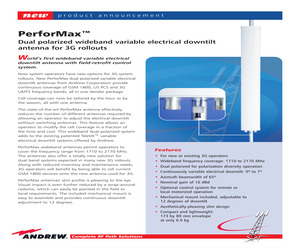
f downtilt * Aesthetically-pleasing slim design * Compact and lightweight: 173 by 89 mm envelope at only 6.0 kg Complete RF Path Solutions new product announcement Specifications for PerforMaxTM dual polarized wideband variable electrical downtilt antenna UMWD-06516-XDM Antenna Type: UMWD-06516-XDM. Description: 65 azimuth beamwidth, 16 dBd gain, variable electrical downtilt, dual polarized GSM 1800/PCS1900/UMTS band panel antenna Electrical Specifications Frequency band, MHz . . . . . . . . . . . . . . . . . . .1710-2170 Gain, dBd (dBi) . . . . . . . . . . . . . . . . . . . . . . . . . .15.6 (17.8) Azimuth beamwidth, degrees . . . . . . . . . . . .65 Elevation beamwidth, degrees . . . . . . . . . . .6.0 Polarization type . . . . . . . . . . . . . . . . . . . . . . .Dual, slant 45 Port to port Isolation, dB . . . . . . . . . . . . . . . .>30 Downtilt, degrees . . . . . . . . . . . . . . . . . . . . . . .Variable, 0 to 7 Impedance, ohms . . . . . . . . . . . . . . . . . . . . . . .50
 2 Pages, 359 KB, Original
1 Section 10-Part Numbering Scheme & Ordering Guide ATC200-Lite Teletilt(R) Remote Control Downtilt System 10.2 Ordering Guide As an example, assume a system is to be ordered for deployment in North America. The site is a three sector site employing three UMWD-06516-XDM antennas. For this example, let's say the distance from the local controller to the junction box is 77m and the distance from the junction box to the three actuators is 2 meters. This system would require the following. Quantity Part Number Description 1 1 3 Optional 1 3 1 or more 2 ATC200-Lite-0004 ATJB200-A01-004 ATM200-001 ATLP-200-001 ATCB-B01-080 ATCB-B01-004 602299 40417 Local Controller 4-Way Junction Box Actuators Lightning Protection Unit 80 Meter Cable 4 Meter Cables Grounding Kit Tiewraps, Bag of 50 The 80 m length is selected since it is the smallest size greater than 77 m. Field fitting of connectors is not recommended in order that reliable, weatherproof connections can be maintained. Although the distance between an
 66 Pages, 1887 KB, Original


