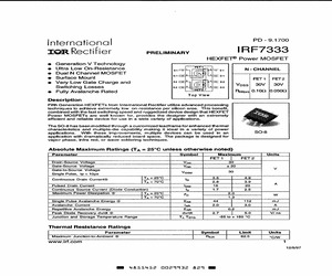
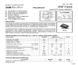
ak Diode Recovery dv/dt @ dv/dt 2.7 | 5.0 Vi ns Junction and Storage Temperature Range Ty, Tsta -55 to + 150 C Thermal Resistance Ratings Parameter Symbol Limit Units Maximum Junction-to-Ambient Resa 62.5 C/W www.irf.com 1 12/8/97 Mm 4855452 0029932 625 MeIRF7333 International TOR Rectifier Electrical Characteristics @ T) = 25C (unless otherwise specified) Parameter Min. | Typ. | Max. {Units Conditions Vierjoss Drain-to-Source Breakdown Voltage ee 2 y | Ves =0V, Ip=250uA . Fer1 | (0.015; DVermpssDT, [Breakdown Voltage Temp. Coefficient FeT2 |= lo 0a21 = |W/C | Reference to 25C, Ip =1mA ret? EX 0.06 | 0.10 Ves = 10V, lp = 2.2A Rosion) Static Drain-to-Source On-Resistance | 0.09|0.20| | | Vas = 4.5V, Ip = 1.0A FET2 | |0.036/0.050 Ves = 10V, Ip = 2.4A @ |0.055|0.080 Vas = 4.5V, Ip = 2.0A Vestn Gate Threshold Voltage Fer : 1.0] | 1! Vv | Vos= Ves, Ip = 250pA ts [Forward Transconductance FET1 _ 12! | 5 | Vog=15V, Ip=3.5A@ FeT2|/ | 3.5) Vos = 15V, Ip = 2.4A J ret1 | | [20 Ipss Drain-to-Source Leakage C
 10 Pages, 611 KB, Scan
040 > a a C - a a 4 un 0.000 0 4 8 12 16 25 50 75 100 125 150 Vag . Gate-to-Source Voltage (V) Starting Ty, Junction Temperature (C) Fig 7. Typical On-Resistance Vs. Gate Fig 8. Maximum Avalanche Energy Voltage Vs. Drain Current 4 www.irf.comInternational IRF7333 TOR Rectifier FET 1 Veg = OV, f= 1MHz Gisg =Cyg +Cgg, Cys SHORTED Crss =Cga Cc - =Cgg + C C, Capacitance (pF) Vag. Gate-to-Source Voltage (V) 0 2 4 6 8 10 ; 10 100 Qg, Total Gate Charge (nC) Vpg , Drain-to-Source Voltage (V} Fig 9. Typical Capacitance Vs. Fig 10. Typical Gate Charge Vs. Drain-to-Source Voltage Gate-to-Source Voltage www.irf.com 5IRF 7333 1000 1000 = =< 5.0 C S BOTTOM 4.5 o = 100 5 100 oO oO 8 2 5 5 Q QoQ a a 2 2 10 = 10 wo s a oO a a 20s PULSE WIDTH _ one 1 Ty = 25C 1 0.1 1 10 100 Vos: Drain-to-Source Voltage (V} Fig 11. Typical Output Characteristics Ip, Drain-to-Source Current (A) Isp , Reverse Drain Current (A) Vog=15V 20us PULSE WIDTH 8 5 Vag , Gate-to-Source Voltage (V} 6 ? 9 io Fig 13. Typical Transfer Characterist
 10 Pages, 192 KB, Scan
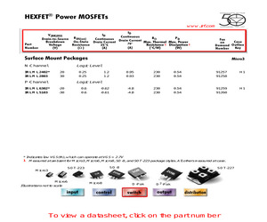
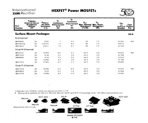
 Demand Outline Number Key Surface Mount Packages SO-8 N-Channel IRF7413 30 0.011 13 9.2 50 2.5 91330 IRF7413A 30 0.0135 12 8.4 50 2.5 91613 IRF9410 30 0.03 7 5.8 50 2.5 91562 IRF7311 20 0.029 6.6 5.3 62.5 2.0 91435 IRF7313 30 0.029 6.5 5.2 62.5 2.0 91480 IRF7333 30 0.10 3.5 2.8 62.5 2.0 91700 30 0.050 4.9 3.9 62.5 2.0 91700 30 0.10 3.5 2.8 62.5 2.0 91559 IRF7314 -20 0.058 -5.3 -4.3 62.5 2.0 91435 IRF7316 -30 0.058 -4.9 -3.9 62.5 2.0 91505 IRF9953 -30 0.25 -2.3 -1.8 62.5 2.0 91560 H4 Dual N-Channel IRF9956 H4 Dual P-Channel * Indicates low VGS(th), which can operate at VGS = 2.7V 1 Measured at ambient for Micro3, Micro6, Micro8, SO-8, and SOT-223 package styles. All others measured at case. SO-8 SOT-223 SOT-227 Micro3 Micro6 Illustrations not to scale Micro8 D-Pak D 2-Pak H4 HEXFET(R) Power MOSFETs www.irf.com ID ID V (BR)DSS Continuous R PD Drain-to-Source R DS(on) Continuous On-State Drain Current Drain Current Max. Thermal Max. Power Breakdown 70 Part Voltage Resistance Resistance 1 Dissipatio
 31 Pages, 453 KB, Original
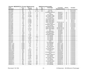
 Harris Harris IR IR IR IR IR IR IR Samsung IR Harris Harris Harris IR IR IR IR IR IR IR Samsung A:Nearest, B:Different Package Power MOSFETs Cross Reference Part Number IRF730S IRF731(R) IRF7311 IRF7313 IRF7314 IRF7316 IRF7317 IRF7319 IRF732(R) IRF733(R) IRF7333 IRF734 IRF7343 IRF737LC IRF7389 IRF740 IRF7401 IRF7403 IRF7404 IRF7406 IRF740A IRF740LC IRF740S IRF741(R) IRF7413 IRF7413A IRF7416 IRF742(R) IRF7421D1 IRF7422D2 IRF743(R) IRF744 IRF7501 IRF7503 IRF7504 IRF7506 IRF7507 IRF7509 IRF750A IRF7601 IRF7603 IRF7604 IRF7606 IRF7805 IRF7807 IRF820 IRF820A IRF820S IRF821(R) IRF822 Revised 1Q '99 VDSS (V) 400 350 20 30 -20 -30 20/-20 30/-30 400 350 30 450 55/-55 300 30/-30 400 20 30 -20 -30 400 400 400 350 30 30 -30 400 30 -20 350 450 20 30 -20 -30 20/-20 30/-30 400 20 30 -20 -30 30 30 500 500 500 450 500 Alphanumerically RDS(ON) ID (ohm) (A) 1 5.5 1 5.5 0.029 6.6 0.029 6.5 0.058 -5.3 0.058 -4.9 0.029/0.058 6.6/-5.3 0.029/0.058 6.5/-4.9 1.5 4.5 1.5 4.5 0.1/0.05 3.5/4.9 1.2 4.9 0.06/0.105 4.7/3.4 0.7
 67 Pages, 163 KB, Original
Ds Demand Outline Number (V) (Q (A) (A) (crw) Surface Mount Packages $0-8 N-Channel IRF9410 30 0.03 7 5.8 50 2.5 91562 H4 IRF7413A 30 0.0135 12 8.4 50 2.5 91613 IRF7413 30 0.011 13 9.2 50 2.5 91330 Dual N-Channel IRF7311 20 0.029 6.6 5.3 62.8 2.0 91435 H4 IRF7333 30 0.10 3.5 2.8 62.5 2.0 91700 [RF9956 30 0.10 3.5 2.8 62.5 91589 30 0.050 49 3.9 62.5 2.0 91700 IRF7313 30 0.029 65 5.2 62.5 2.0 91480 Dual P-Channel [RF7314 -20 0.058 -5,3 -43 62.5 20 91435 H4 IRF9953 -30 6.25 -2.3 -1.8 62.5 2.0 91560 IRF7316 -30 0.058 4.9 3.9 62.5 2.0 91505 * Indicates low VGSth), which can operate at VGS = 2.7 1. Measured at ambient for Micro3, Micro6, Micro8, SO-8. and SOT-223 package styles. All others measured at case. SOT-223 SO0-8 e222 Micro6 Illustrations not to scale SOT-227 Micro8 D-Pak D*-Pak www.irf.com E-13
 1 Pages, 29 KB, Scan


