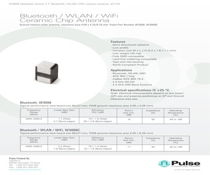
W3008C Features - Omni directional radiation - Low profile - Compact size W x L x H (3.2 x 1.6 x 1.1 mm) - Low weight (33 mg) - Fully SMD compatible - Lead free soldering compatible - Tape and reel packing - RoHS Compliant Product Applications - Bluetooth, WLAN, WiFi - IEEE 802.11b/g - ZigBee IEEE 802.15.4 - 2.4 GHz WLAN - 2.4 GHz ISM Band Systems Electrical specifications @ +25 C Note: Electrical characteristics depend on test board (GP) size and antenna positioning on GP and Ground Clearance area size. Bluetooth, W3008 Typical performance (test board size 80x37 mm, PWB ground clearance area 4.00 x 4.25 mm) Frequency Range [MHz] Linear Max Gain [dBi] Efficiency [%] / [dB] Return loss min. [dB] Impedance [] Operating Temperature [C] 2400-2483.5 1.7 (Peak) 0.7 (Band edges) 70 / -1.6 (Peak) 55 / -2.6 (Band edges) -8 50 -40 to +85 Bluetooth / WLAN / WiFi, W3008C Typical performance (test board size 80x37 mm, PWB ground clearance area 4.00 x 6.25 mm) Frequency Range [MHz] Linear Max Gain
 8 Pages, 1670 KB, Original
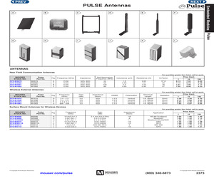
in (dBi) Impedance (Nom) D E F D 2.4 - 2.5 2.4 - 2.5 2.4 & 5.0 868 - 928 2.0 4.9 2.0 3.0 50 50 50 50 VSWR 2.0 2.0 2.0 2.0 Polarization Vertical Vertical Vertical Vertical Surface Mount Antennas for Wireless Devices MOUSER STOCK NO. 673-W3006 673-W3008 673-W3008C 673-W3010 673-W3011A 673-W3012 673-W3110 Pulse Part No. W3006 W3008 W3008C W3010 W3011A W3012 W3110 (c) Copyright 2016 Mouser Electronics Electrical Length 1/4, 1/4, 1/4, 1/4, Radiation dipole dipole dipole dipole Omni Omni Omni Omni Price Each 10 3.24 5.88 8.25 6.87 100 2.70 4.90 6.94 5.65 For quantities greater than listed, call for quote. Fig. Frequency (GHz) Gain (dBi) Impedance (Nom) Application G H H I J K L 10.0x3.2x1.5 3.2x1.6x1.1 3.2x1.6x1.1 10.0x3.2x2.0 3.2x1.6x1.1 10x3.2x4 5.0x2.5x5.5 2.4 and 5/5.8 GHz 2.4-2.5 GHz 2.4-2.5 GHz 1575.4 MHz 1575.4 MHz 806-960 MHz 1575.4 MHz -18 -8 -11 -18 -12 -6 -16 WLAN Dualband Bluetooth Bluetooth/WLAN/WiFi GPS GPS ISM 900 GPS mouser.com/pulse 1 3.38 6.13 8.63 7.63 (800) 346-6873 Pri
 1 Pages, 250 KB, Original
 3.7 80 55 2400-2483.5 -13 2.5 1.3 72 60 4950-5850 -8 5.7 3.3 78 55 2400-2483.5 -8 3.2 2.5 80 70 1575.42+ 10 -10 2.5 1.5 75 65 2400-2483.5 -11 -0.7 -1.7 80 70 1575.42 + 10 -15 -2.0 70 60 2400-2483.5 -11 2.5 1.5 85 80 4950-5850 -6 3.5 1.0 70 50 W3001 W3008 W3008C W3006 W3078 W3079 W3056 W3064C Ceramic chip Single WiFi, BT, Zigbee Dual WiFi Peak Gain (dBi) Band edges W3000 Combo GPS+WiFi or ISM 868/915 + WiFi RL Min. (dB) ME requirement 2400-2483.5 70 0 60 43 50 W3095 W3320 1559-1610.5 -10 1.5 0.8 75 60 863-928 -8 1.5 0.8 67 55 2400-2500 -6 3.4 1.4 61 45 Antenna DIM. (LxWxH,mm) 7 x 1.6 x 1.6 @ Stock Stock 12 x 9.5 10 x 3.2 x 2 4.6 x 3.95 *NOTE: 1. Recommended minimum GND dimensions of PIFA type and Monopole's are roughly 40x20mm and 30x20mm (or 40x11mm), respectively. Need to construct matching values to optimize antenna performance on surrounding mechanics and materials. 2. Pulse offers very unique GPS+WiFi combo antennas on single ceramic chip (10x3.2x1.5mm). There are three different types of co
 43 Pages, 5697 KB, Original
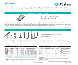
imple and easy to mount. Surface Mount Antennas for Wireless Devic es 1, 2 Application/ Part Number Zigbee, ISM Monopole Ceramic W30006 6 Zigbee, ISM Monopole Ceramic W3001 6 WLAN Dualband Ceramic W3006 Bluetooth Ceramic W3008 Bluetooth/ WLAN/WiFi Ceramic W3008C GPS Ceramic W3009 Antenna Size 4 Mount Type 3 (mm) Frequency Range (MHz) RHCP Gain 5 (dBic) Max Gain (dBi) Efficiency (%/dB) Return Loss (dB MIN) 7x1.6x1.6 SMD GC 11x6 2400, 868, 1575 and other -- 2.5 (peak) 75/-1.55 -18 10x3.2x4mm SMD, GC 10.8x6.25 2400 and other -- 1.5 (peak) 75/-1.25 -6 2400-2483.5 5150-5850 -- 3,2 (peak) 2,7 (band edges) 4,2 (peak) 3,0 (band edges) 70/-1,55 (peak) 65/-1,85 (band edges) 80/-0,95 (peak) 70/-1,55 (band edges) -8 10.0x3.2x1.5 SMD, GC area 11.60x6.00 3.2x1.6x1.1 SMD, GC area 4.00x4.25 2400-2483.5 -- 1,7 (peak) 0,7 (band edges) 70/-1,6 (peak) 55/-2,6 (band edges) -8 3.2x1.6x1.1 SMD, GC area 4.00x6.25 2400-2483.5 -- 2,2 (peak) 1,9 (band edges) 75/-1,3 (peak) 70/-1,6 (band edges) -11 10.0x3.2x4.0 SMD, GC area
 7 Pages, 174 KB, Original
 and many more. Page 32 R77 22K C83 33nF VCC-RF C126 C127 100nF 100nF 100nF R78 10K RF-CE RF-CS# SPI1-SCK SPI1-MOSI SPI1-MISO VCC-3.3V C128 C129 C130 C131 100nF 100nF 100nF 100nF C132 C133 10nF 10nF R79 10K U16 1 2 3 4 5 R80 27 R81 10K RF-INT# VCC-CORE A1 W3008C VDD CE VSS CSN nRF24L01P ANT2 SCK ANT1 MOSI VDD_PA MISO L4 3.9nH 15 14 13 12 11 1.5pF L5 8.2nH C85 N.M. L6 2.7nH C86 2.2nF VREF C134 C135 C136 C137 C138 C139 10nF 100nF 1uF 2.2uF 100nF 10nF R82 1M VCC-RF TM4C129LNCZAD U6 V6 W6 T7 V7 W7 T8 U8 RF-CS# C8 E7 H17 F16 F18 E17 N1 K5 PH0 PH1 PH2 PH3 PH4 PH5 PH6 PH7 PJ0 PJ1 PJ2 PJ3 PJ4 PJ5 PJ6 PJ7 PORT G PORT K PK0 PK1 PK2 PK3 PK4 PK5 PK6 PK7 PL0 PL1 PL2 PL3 PL4 PL5 PL6 PL7 PM0 PM1 PM2 PM3 PM4 PM5 PM6 PM7 J1 J2 K1 K2 U19 V17 V16 W16 P18 M17 U18 P19 G16 H19 G18 J18 H18 G19 C18 B18 K18 K19 L18 L19 M18 G15 N19 N18 C93 22pF V15 V14 W13 V13 W15 C88 C89 C90 C91 10uF 100nF 100nF 100nF OSC0 U1A RST HIB WAKE VBAT OSC0 GNDX2 OSC1 SY ST E M P4 R2 R1 T1 R3 T2 U2 V2 PG0 PG1 PG2 PG3 PG4 PG5 PG6 PG7 PORT H SPI1-
 49 Pages, 5776 KB, Original
ices 1, 2 Application/ Part Number Antenna Size 4 Mount Type 3 (mm) WLAN Dualband SMD, 10.0x3.2x1.5 Ceramic GC area 11.60x6.00 W3006 Bluetooth SMD, Ceramic 3.2x1.6x1.1 GC area 4.00x4.25 W3008 Bluetooth/ WLAN/WiFi SMD, 3.2x1.6x1.1 Ceramic GC area 4.00x6.25 W3008C GPS SMD, Ceramic 10.0x3.2x2.0 GC area 10.80x6.25 W3010 Satellite Radio SMD, Ceramic 3.2x1.6x1.1 GC area 4.00x4.25 W3017 DMB-S SMD, Ceramic 3.2x1.6x1.1 GC area 4.00x4.25 W3018 WiMAX SMD, Ceramic 3.2x1.6x1.1 GC area 4.00x6.25 W3020 1. All antennas are RoHS Compliant 2. Impedance 50 , operating temperature -40C to +85C 3. GC = Ground Clearance, mm 2 Frequency Range (MHz) RHCP Gain 5 (dBic) Max Gain (dBi) Efficiency (%/dB) Return Loss (dB MIN) 2400-2483.5 5150-5850 3,2 (peak) 2,7 (band edges) 4,2 (peak) 3,0 (band edges) 70 / -1,55 (peak) 65 / -1,85 (band edges) 80 / -0,95 (peak) 70 / -1,55 (band edges) -8 2400-2483.5 1,7 (peak) 0,7 (band edges) 70 / -1,6 (peak) 55 / -2,6 (band edges) -8 2400-2483.5 2,2 (peak) 1,9 (band edges) 75 / -1,3 (peak)
 6 Pages, 174 KB, Original
mic GC area 11.60x6.00 5150-5850 4,2 (peak) 80/-0,95 (peak) -10 W3006 3,0 (band edges) 70/-1,55 (band edges) Bluetooth/ WLAN/WiFi SMD, 2,2 (peak) 75/-1,3 (peak) -- 3.2x1.6x1.1 2400-2483.5 -11 Ceramic GC area 4.00x6.25 1,9 (band edges) 70/-1,6 (band edges) W3008C GPS SMD, 0.7 (peak) 3 (peak) 80/-1,25 (peak) Ceramic 10.0x3.2x4.0 1575.42 10 -10 GC area 10.80x6.25 0.3 (band edges) 2,5 (band edges) 70/-1,25 (band edges) W3009 1. All antennas are RoHS Compliant 2. Impedance 50 W, operating temperature -40C to +85C 3. GC = Ground Clearance, mm 4. Millimeters (mm) 5. -- = NA 6. Monopole antenna performance is linked to different tuning circuit recommendations for the variety of applications. Consult the data sheet for more information Pulse Jack *Table for "SMD Antennas for Wireless Devices" continued on next page G003.Y (6/11) Electronics www.pulseelectronics.com 3 ANTENNAS ANTENNAS FOR WIRELESS DEVICES (continued) Internal and Surface Mount Antenna Solutions (continued) Surface Mount Antennas for Wirel
 7 Pages, 788 KB, Original
6 (peak) Ceramic 3.2x1.6x1.1 2400-2483.5 -- -8 GC area 4.00x4.25 0,7 (band edges) 55/-2,6 (band edges) W3008 Bluetooth/ WLAN/WiFi SMD, 2,2 (peak) 75/-1,3 (peak) -- 3.2x1.6x1.1 2400-2483.5 -11 Ceramic GC area 4.00x6.25 1,9 (band edges) 70/-1,6 (band edges) W3008C GPS SMD, 0.7 (peak) 3 (peak) 80/-1,25 (peak) Ceramic 10.0x3.2x4.0 1575.42 10 -10 GC area 10.80x6.25 0.3 (band edges) 2,5 (band edges) 70/-1,25 (band edges) W3009 Pulse Jack 1. All antennas are RoHS Compliant 2. Impedance 50 W, operating temperature -40C to +85C 3. GC = Ground Clearance, mm 4. Millimeters (mm) 5. -- = NA 6. Monopole antenna performance is linked to different tuning circuit recommendations for the variety of applications. Consult the data sheet for more information *Table for "SMD Antennas for Wireless Devices" continued on next page G003.Y (6/11) Electronics www.pulseelectronics.com 3 antennas Antennas for wireless devices (continued) Internal and Surface Mount Antenna Solutions (continued) Surface Mount Antennas for Wirel
 7 Pages, 936 KB, Original
015 10x3.2x4mm Ceramic SMD, GC 10.8x6.25 2400 and other N/A 1.5 (peak) 75/-1.25 -6 WLAN Dualband W3006 10.0x3.2x1.5 Ceramic SMD, GC area 11.60x6.00 2400-2483.5 5150-5850 N/A 3,2 (peak) 4,2 (peak) 70/-1,55 (peak) 80/-0,95 (peak) -8 -10 Bluetooth/ WLAN/WiFi W3008C 3.2x1.6x1.1 Ceramic SMD, GC area 4.00x6.25 2400-2483.5 N/A 2,2 (peak) 75/-1,3 (peak) -11 GPS W3009 10.0x3.2x4.0 Ceramic SMD, GC area 10.80x6.25 1575.42 10 0.7 (peak) 0.3 (band edges) 3 (peak) 80/-1,25 (peak) -10 ISM W3013 10x3.2x4 Ceramic GC area 10.8x8.25 868-870 -- 1.5 65 -11 WiFi & GPS W3056 10x3.2x1.5 Ceramic GC area 10.8x6.25 (Notch) 2400-2483.5 / 1575.42 -- 3.2 / 2.5 80 / 75 -8 / -10 WiFi & GPS W3064C 10x3.2x1.5 Ceramic GC area 10.8x6.4 (Divided) 2400-2483.5 / 1575.42 -- -0.7 / -1 80 / 70 -11 / -15 GPS W3213 13x13x4 Patch -- 1575.42 -1.5 -- -- -13 GPS W3216 13x13x5 Patch -- 1575.42 -2 -- 60 -7 GPS W3099 25x25x4 Patch -- 1575.42 3.5 -- -- -14 1. All antennas are RoHS Compliant 2. Operating temperature -40C to +85C 3. GC = Ground Clea
 60 Pages, 12906 KB, Original
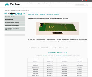
 BELOW TO CHOOSE A DEMO BOARD CERAMIC ANTENNAS Please click HERE to view all of our Ceramic Antennas via our Product Finder W3000-K W3014-K W3047A-K W3112-K W3001-K W3016-K W3056-K W3113-K W3004-K W3017-K W3064A-K W3117-K W3006-K W3020-K W3064C-K W3118A-K W3008C-K W3024-K W3070-K W3126-K W3008-K W3028-K W3078-K W3300-K W3009-K W3029-K W3079-K W3320-K W3010-K W3030-K W3095-K W3330-K W3011-A-K W3031-K W3108-K W3510-K W3011-K W3032-K W3110-K W3530-K W3012-K W3040-K W3112A-K W3544B-K W3013-K W3043-K W3112-K W3796-K Can't find what you are looking for? Call 1-800-ANTENNA (268-3662) Email us at info@larsen.pulseeng.com antennas.as for ASIA antennas.eu for EUROPE antennas.us for UNITED STATES. (c) 2017 Pulse Electronics All rights reserved. Terms of Use | Safe Harbor Policy | Privacy Policy | Terms and Conditions of Sale
 2 Pages, 1279 KB, Original


