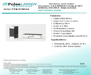
W3008 Features: * 2400-2483.5MHz * Size: 3.2 x 1.6 x 1.1mm * Efficiency: 66 % * Gain: 1.1 dBi * Polarization: Linear * Power Handling: 5W * RoHS Compliant * Moisture Sensitivity Level MSL3 Applications: * Bluetooth, BLE, Zigbee, WiFi * 2.4GHz ISM band radios All dimensions are in mm / inches Issue: 1823 In the effort to improve our products, we reserve the right to make changes judged to be necessary. CONFIDENTIAL AND PROPRIETARY INFORMATION This document contains confidential and proprietary information of Pulse Electronics, Inc. (Pulse) and is protected by copyright, trade secret and other state and federal laws. Its receipt or possession does not convey any rights to reproduce, disclose its contents, or to manufacture, use or sell anything it may describe. Reproduction, disclosure or use without specific written authorization of Pulse is strictly forbidden. For more information: Pulse Worldwide Headquarters 15255 Innovation Drive #100 San Diego, CA 92128 USA Tel:1-858-674-8100 Pulse/Larsen Ant
 14 Pages, 1080 KB, Original
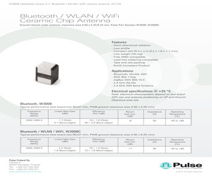
W3008 Datasheet version 2.7. Bluetooth / WLAN / WiFi ceramic antenna. (01/10) Bluetooth / WLAN / WiFi Ceramic Chip Antenna Ground cleared under antenna, clearance area 4.00 x 4.25/6.25 mm. Pulse Part Number W3008, W3008C Features - Omni directional radiation - Low profile - Compact size W x L x H (3.2 x 1.6 x 1.1 mm) - Low weight (33 mg) - Fully SMD compatible - Lead free soldering compatible - Tape and reel packing - RoHS Compliant Product Applications - Bluetooth, WLAN, WiFi - IEEE 802.11b/g - ZigBee IEEE 802.15.4 - 2.4 GHz WLAN - 2.4 GHz ISM Band Systems Electrical specifications @ +25 C Note: Electrical characteristics depend on test board (GP) size and antenna positioning on GP and Ground Clearance area size. Bluetooth, W3008 Typical performance (test board size 80x37 mm, PWB ground clearance area 4.00 x 4.25 mm) Frequency Range [MHz] Linear Max Gain [dBi] Efficiency [%] / [dB] Return loss min. [dB] Impedance [] Operating Temperature [C] 2400-2483.5 1.7
 8 Pages, 1670 KB, Original
 AUTO INSERTIBLE WIRE WRAP 2 LEVEL IRE ARAP UFVEL TOMPONENT CAPS 9 SPOUGS eo dF AUER Ae a Pe | ea) ee rr wy of jie q! i i HL jae PE W30S06T W30S506AT W30606T2 W30606T3 WE60S06SPT W60506TPT W300506T [| w30s06G W30806AG W30606G2 W30606G3 W60S06SPG WE0S06TPG W300806G W30508T W30508AT W30608T2 W30608T3 We60508SPT We0S08TPT W300508T (| w20s08c W30808AG W30608G2 W30608G3 W60508SPG W60S08TPG W300508G W308 14T W308 14AT W30614T2 W30614T3 W605 14SPT W605 14TPT W3005 14T [| w30814G W308 14AG W306 14G2 W30614G3 W608 14SPG W605 14TPG W300514G W305 16T W308 16AT W30616T2 W30616T3 W605 16SPT W605 16TPT W3005 16T [i] w30s16G W30816AG W306 16G2 W30616G3 W605 16SPG W605 16TPG W300816G W305 18T W308 18AT W30618T2 W306 18T3 W605 18SPT W605 18TPT W3005 18T U W30518G W308 18AG W306 18G2 W30618G3 W605 18SPG W608 18TPG W3008 18G W30520T W30S20AT W30620T2 W30620T3 We60S20SPT W60520TPT W300520T ' | w30820G W30820AG W30620G2 W30620G3 W60520SPG W60S20TPG W300820G v W30520/4T W30820/4A
 22 Pages, 1601 KB, Scan
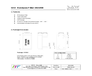
ion : Kovar, Au Plated I T F Co., Ltd. 102-901, Bucheon Technopark 364, Samjeong-Dong, Ojeong-Gu, Bucheon-City, Gyounggi-Do, Korea 421-809 2.50.2 2. Package Dimension Input 5 Output 2, 4 Ground Other Case ground Part No. 202195B Rev. Date 2004-04-02 Rev. NW3008-CS02 1/5 SAW Bandpass Filter 202195B 3. Specifications Fo = 70.0 MHz Terminating source impedance : 50 and matching network Terminating load impedance : 50 and matching network Minimum Typical Maximum MHz - 70.0 - dB - 24.0 25.5 1dB Bandwidth MHz - 18.9 - 3dB Bandwidth MHz 18.9 19.1 - 40dB Bandwidth MHz - 20.0 20.1 dB - 0.75 1.0 Group Delay Variation (Fo +/- 9.22 MHz) nsec - 60 120 Absolute Delay usec - 3.1 - Ultimate Rejection dB 50 55 - ppm/C - -72.0 - Center Frequency Insertion Loss Amplitude Ripple (Fo +/- 9.22 MHz) Temperature Coefficient of Frequency Notes : 1) All specifications are based on the matching schematic shown below 2) All specifications are measured by Agilent Network analyzer and full 2 port calibration at room temperatu
 5 Pages, 182 KB, Original
mine phenol Copper with silver plating Silver alloy plus copper with silver plating Copper with tin plating Environmental Data Operating Temp Range: -10C through +70C (+14F through +158F) Sealing: Dustproof cover of silicone rubber on SW3006A, SW3007A, & SW3008A Installation Maximum Panel Thickness: Shown with following drawings Soldering Time & Temperature: Manual Soldering: See Profile A in Supplement section. Standards & Certifications R R V D E UL Recognized: Designated with UL recognized symbol beside part numbers on following pages See Supplement section to find UL rating details. UL File No. WOYR2.E44145 Add "/U" to end of part number to order UL mark on switch. C-UL Recognized: Designated with C-UL recognized symbol beside part numbers on following pages See Supplement section to find C-UL rating details. C-UL File No. WOYR8.E44145 Add "/C-UL" to end of part number to order C-UL mark on switch. CSA Certified: Designated with CSA certified symbol beside part numbers on following pages See
 4 Pages, 150 KB, Original
mine phenol Copper with silver plating Silver alloy plus copper with silver plating Copper with tin plating Environmental Data Operating Temp Range: -10C through +70C (+14F through +158F) Sealing: Dustproof cover of silicone rubber on SW3006A, SW3007A, & SW3008A Slides Rotaries Keylocks Programmable Illuminated PB Pushbuttons Rockers Toggles Series SW Maximum Panel Thickness: Shown with following drawings Soldering Time & Temperature: Manual Soldering: See Profile A in Supplement section. Standards & Certifications UL: File No. E44145 - Recognized only when ordered with marking on switch. Add "/U" or "/CUL" to end of part number to order UL recognized switch. UL or cULus recognition designated beside part numbers on following pages. See Supplement section to find UL or cULus rating details. CSA: File No. 023535_0_000 - Certified only when ordered with marking on switch. Add "/C" to end of part number to order CSA certified switch. CSA certification designated beside part numbers on following page
 5 Pages, 403 KB, Original
mine phenol Copper with silver plating Silver alloy plus copper with silver plating Copper with tin plating Environmental Data Operating Temp Range: -10C through +70C (+14F through +158F) Sealing: Dustproof cover of silicone rubber on SW3006A, SW3007A, & SW3008A Slides Rotaries Keylocks Programmable Illuminated PB Pushbuttons Rockers Toggles Series SW Maximum Panel Thickness: Shown with following drawings Soldering Time & Temperature: Manual Soldering: See Profile A in Supplement section. Standards & Certifications UL: File No. E44145 - Recognized only when ordered with marking on switch. Add "/U" or "/CUL" to end of part number to order UL recognized switch. UL or cULus recognition designated beside part numbers on following pages. See Supplement section to find UL or cULus rating details. CSA: File No. 023535_0_000 - Certified only when ordered with marking on switch. Add "/C" to end of part number to order CSA certified switch. CSA certification designated beside part numbers on following page
 4 Pages, 391 KB, Original
-6 4.3 3.7 80 55 2400-2483.5 -13 2.5 1.3 72 60 4950-5850 -8 5.7 3.3 78 55 2400-2483.5 -8 3.2 2.5 80 70 1575.42+ 10 -10 2.5 1.5 75 65 2400-2483.5 -11 -0.7 -1.7 80 70 1575.42 + 10 -15 -2.0 70 60 2400-2483.5 -11 2.5 1.5 85 80 4950-5850 -6 3.5 1.0 70 50 W3001 W3008 W3008C W3006 W3078 W3079 W3056 W3064C Ceramic chip Single WiFi, BT, Zigbee Dual WiFi Peak Gain (dBi) Band edges W3000 Combo GPS+WiFi or ISM 868/915 + WiFi RL Min. (dB) ME requirement 2400-2483.5 70 0 60 43 50 W3095 W3320 1559-1610.5 -10 1.5 0.8 75 60 863-928 -8 1.5 0.8 67 55 2400-2500 -6 3.4 1.4 61 45 Antenna DIM. (LxWxH,mm) 7 x 1.6 x 1.6 @ Stock Stock 12 x 9.5 10 x 3.2 x 2 4.6 x 3.95 *NOTE: 1. Recommended minimum GND dimensions of PIFA type and Monopole's are roughly 40x20mm and 30x20mm (or 40x11mm), respectively. Need to construct matching values to optimize antenna performance on surrounding mechanics and materials. 2. Pulse offers very unique GPS+WiFi combo antennas on single ceramic chip (10x3.2x1.5mm). There are three di
 43 Pages, 5697 KB, Original
mine phenol Copper with silver plating Silver alloy plus copper with silver plating Copper with tin plating Environmental Data Operating Temp Range: -10C through +70C (+14F through +158F) Sealing: Dustproof cover of silicone rubber on SW3006A, SW3007A, & SW3008A Slides Rotaries Keylocks Programmable Illuminated PB Pushbuttons Rockers Toggles GENERAL SPECIFICATIONS FOR SW3000s Maximum Panel Thickness: Shown with following drawings Soldering Time & Temperature: Manual Soldering: See Profile A in Supplement section. Standards & Certifications UL: File No. E44145 - Recognized only when ordered with marking on switch. Add "/U" or "/CUL" to end of part number to order UL recognized switch. UL or cULus recognition designated beside part numbers on following pages. See Supplement section to find UL or cULus rating details. CSA: File No. 023535_0_000 - Certified only when ordered with marking on switch. Add "/C" to end of part number to order CSA certified switch. CSA certification designated beside part
 4 Pages, 366 KB, Original
y (GHz) Gain (dBi) Impedance (Nom) D E F D 2.4 - 2.5 2.4 - 2.5 2.4 & 5.0 868 - 928 2.0 4.9 2.0 3.0 50 50 50 50 VSWR 2.0 2.0 2.0 2.0 Polarization Vertical Vertical Vertical Vertical Surface Mount Antennas for Wireless Devices MOUSER STOCK NO. 673-W3006 673-W3008 673-W3008C 673-W3010 673-W3011A 673-W3012 673-W3110 Pulse Part No. W3006 W3008 W3008C W3010 W3011A W3012 W3110 (c) Copyright 2016 Mouser Electronics Electrical Length 1/4, 1/4, 1/4, 1/4, Radiation dipole dipole dipole dipole Omni Omni Omni Omni Price Each 10 3.24 5.88 8.25 6.87 100 2.70 4.90 6.94 5.65 For quantities greater than listed, call for quote. Fig. Frequency (GHz) Gain (dBi) Impedance (Nom) Application G H H I J K L 10.0x3.2x1.5 3.2x1.6x1.1 3.2x1.6x1.1 10.0x3.2x2.0 3.2x1.6x1.1 10x3.2x4 5.0x2.5x5.5 2.4 and 5/5.8 GHz 2.4-2.5 GHz 2.4-2.5 GHz 1575.4 MHz 1575.4 MHz 806-960 MHz 1575.4 MHz -18 -8 -11 -18 -12 -6 -16 WLAN Dualband Bluetooth Bluetooth/WLAN/WiFi GPS GPS ISM 900 GPS mouser.com/pulse 1 3.
 1 Pages, 250 KB, Original
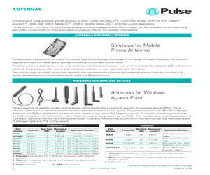
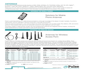
lse's antenna products makes them simple and easy to mount. Surface Mount Antennas for Wireless Devic es 1, 2 Application/ Part Number Zigbee, ISM Monopole Ceramic W30006 6 Zigbee, ISM Monopole Ceramic W3001 6 WLAN Dualband Ceramic W3006 Bluetooth Ceramic W3008 Bluetooth/ WLAN/WiFi Ceramic W3008c GPS Ceramic W3009 Antenna Size 4 Mount Type 3 (mm) Frequency Range (MHz) RHCP Gain 5 (dBic) Max Gain (dBi) Efficiency (%/dB) Return Loss (dB MIN) 7x1.6x1.6 SMD GC 11x6 2400, 868, 1575 and other -- 2.5 (peak) 75/-1.55 -18 10x3.2x4mm SMD, GC 10.8x6.25 2400 and other -- 1.5 (peak) 75/-1.25 -6 2400-2483.5 5150-5850 -- 3,2 (peak) 2,7 (band edges) 4,2 (peak) 3,0 (band edges) 70/-1,55 (peak) 65/-1,85 (band edges) 80/-0,95 (peak) 70/-1,55 (band edges) -8 10.0x3.2x1.5 SMD, GC area 11.60x6.00 3.2x1.6x1.1 SMD, GC area 4.00x4.25 2400-2483.5 -- 1,7 (peak) 0,7 (band edges) 70/-1,6 (peak) 55/-2,6 (band edges) -8 3.2x1.6x1.1 SMD, GC area 4.00x6.25 2400-2483.5 -- 2,2 (peak) 1,9 (band edges) 75/-1,3 (peak) 70
 7 Pages, 174 KB, Original
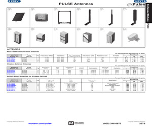
 W1900 W1910 W1910 2.4GHz Band; 4900 - 5825MHz 824 - 960MHz; 1710 - 1990MHz; 1920 - 2170MHz 824 - 960MHz; 1710 - 1990MHz; 1920 - 2170MHz 5 W3000 W3000 6 W3001 W3001 2.4GHz Band CERAMIC ANTENNA 4 7 W3006 W3006 2.4GHz Band; 5150 -5850MHz CERAMIC ANTENNA 4 8 W3008 W3008 2.4GHz Band CERAMIC ANTENNA 6 9 W3010 W3010 GPS CERAMIC ANTENNA 4 10 W3011 W3011 GPS CERAMIC ANTENNA 6 11 W3043 W3043 GPS; 2.4GHz Band CERAMIC ANTENNA 6 W3056 W3056 GPS; 2.4GHz Band CERAMIC ANTENNA 4 W3070 W3070 4 W3073 W3073 880 - 960MHz; 1710 - 1880MHz CERAMIC ANTENNA 824 - 849MHz / 1710 -2170MHz; 880 - 960MHz / 1710 -2170MHz CERAMIC ANTENNA 15 W3078 W3078 2.4GHz Band; 4950 -5850MHz CERAMIC ANTENNA 4 16 W3079 W3079 2.4GHz Band; 5150 -5850MHz CERAMIC ANTENNA 4 17 W3092 W3092 6 W3095 W3095 2.4GHz Band CERAMIC ANTENNA 2.4GHz Band; 4900 - 5925MHz; GPS / GLONASS CERAMIC ANTENNA 19 W3108 W3108 2.4GHz Band HELICAL ANTENNA 4 20 W3110 W3110 GPS HELICAL ANTENNA 4 21 W3216 W3216 GPS / GLONASS CERAMIC ANTENNA 4 22 W3320 W3320 863
 5 Pages, 638 KB, Original
3.2x1.5 Ceramic GC area 11.60x6.00 5150-5850 4,2 (peak) 80/-0,95 (peak) -10 W3006 3,0 (band edges) 70/-1,55 (band edges) Bluetooth SMD, 1,7 (peak) 70/-1,6 (peak) Ceramic 3.2x1.6x1.1 2400-2483.5 -- -8 GC area 4.00x4.25 0,7 (band edges) 55/-2,6 (band edges) W3008 Bluetooth/ WLAN/WiFi SMD, 2,2 (peak) 75/-1,3 (peak) -- 3.2x1.6x1.1 2400-2483.5 -11 Ceramic GC area 4.00x6.25 1,9 (band edges) 70/-1,6 (band edges) W3008c GPS SMD, 0.7 (peak) 3 (peak) 80/-1,25 (peak) Ceramic 10.0x3.2x4.0 1575.42 10 -10 GC area 10.80x6.25 0.3 (band edges) 2,5 (band edges) 70/-1,25 (band edges) W3009 Pulse Jack 1. All antennas are RoHS Compliant 2. Impedance 50 W, operating temperature -40C to +85C 3. GC = Ground Clearance, mm 4. Millimeters (mm) 5. -- = NA 6. Monopole antenna performance is linked to different tuning circuit recommendations for the variety of applications. Consult the data sheet for more information *Table for "SMD Antennas for Wireless Devices" continued on next page G003.Y (6/11) Electronics w
 7 Pages, 936 KB, Original
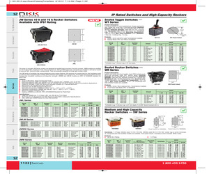
9 12.15 12.81 *S=Solder Lug; T=Screw Lug; L=8" wire leads; F=0.250" Quick Connect (Q.C.). Medium and High Capacity Rocker Switches -- SW Series RoHS (3.5) Dia Typ .138 (3.5) Dia Typ .138 (37.0) 1.457 (28.0) 1.102 JWLW21RA1A JWLW21RC1A JWLW22RAA JWLW22RCA SW3008A JWMW11RA1A JWMW11RA2A JWMW11RAA JWMW21RA1A JWMW21RA2A SPST SPST SPST DPST DPST On-None-Off On-None-Off On-None-Off On-None-Off On-None-Off Black Black Black Black Black Horizontal Vertical None Horizontal Vertical 7.15 7.15 6.20 8.85 8.85 6.55 6.55 5.68 8.12 8.31 6.05 6.05 5.25 7.49 7.70 Stock No. Mfr.'s Type Contact Form Barrier Color Inscription 70234774 70234775 70234760 70191987 70234761 70234762 70234763 70234764 70234765 JWM11BA1A-A JWM11BA2A-A JWM11RA1A JWM11RA2A JWM11RAA JWM21BA2A-A JWM21RA1A JWM21RA2A JWM22RAA SPST SPST SPST SPST SPST DPST DPST DPST DPDT Black Black No Barrier No Barrier No Barrier Black No Barrier No Barrier No Barrier Horizontal Vertical Horizontal Vertical None Vertical Horizontal Vertical None 1122 SWITCHES E
 1 Pages, 712 KB, Original
them simple and easy to mount. Surface Mount Antennas for Wireless Devices 1, 2 Application/ Part Number Antenna Size 4 Mount Type 3 (mm) WLAN Dualband SMD, 10.0x3.2x1.5 Ceramic GC area 11.60x6.00 W3006 Bluetooth SMD, Ceramic 3.2x1.6x1.1 GC area 4.00x4.25 W3008 Bluetooth/ WLAN/WiFi SMD, 3.2x1.6x1.1 Ceramic GC area 4.00x6.25 W3008c GPS SMD, Ceramic 10.0x3.2x2.0 GC area 10.80x6.25 W3010 Satellite Radio SMD, Ceramic 3.2x1.6x1.1 GC area 4.00x4.25 W3017 DMB-S SMD, Ceramic 3.2x1.6x1.1 GC area 4.00x4.25 W3018 WiMAX SMD, Ceramic 3.2x1.6x1.1 GC area 4.00x6.25 W3020 1. All antennas are RoHS Compliant 2. Impedance 50 , operating temperature -40C to +85C 3. GC = Ground Clearance, mm 2 Frequency Range (MHz) RHCP Gain 5 (dBic) Max Gain (dBi) Efficiency (%/dB) Return Loss (dB MIN) 2400-2483.5 5150-5850 3,2 (peak) 2,7 (band edges) 4,2 (peak) 3,0 (band edges) 70 / -1,55 (peak) 65 / -1,85 (band edges) 80 / -0,95 (peak) 70 / -1,55 (band edges) -8 2400-2483.5 1,7 (peak) 0,7 (band edges) 70 / -1,6 (peak)
 6 Pages, 174 KB, Original


