Read (8/16 bits) (3 x fXX/fCANMODE + 1)/(2 + j) (MIN.) Note 3 (4 x fXX/fCANMODE + 1)/(2 + j) (MAX.) Write 1 C0GMCS, C0CTRL C0RGPT, C0TGPT Note 3 Read/write C0MDATA01m, C0MDATA0m, C0MDATA1m, C0MDATA23m, C0MDATA2m, C0MDATA3m, C0MDATA45m, C0MDATA4m, C0MDATA5M, C0MDATA67m, C0MDATA6m, C0MDATA7m, C0MDLCm, Note 3 Note 3 Note Note 3 Note 3 Note 3 Note 3 Note 3 C0MCONFm, C0MIDLm, C0MIDHm CRC CRCD Number of clocks necessary for access = 3 + i + j + (2 + j) x k Notes 1. I2C bus versions (Y products) only 2. CAN controller versions only 3. Digits below the decimal point are rounded up. Caution Accessing the above registers is prohibited in the following statuses. If a wait cycle is generated, it can only be cleared by a reset. * When the CPU operates with the subclock and the main clock oscillation is stopped * When the CPU operates with the internal oscillation clock User's Manual U16541EJ5V1UD 95 CHAPTER 3 CPU FUNCTION Remark fXX: Main clock frequency = fXX fCANMOD: CAN module system clock fCAN: Su
 1160 Pages, 7699 KB, Original
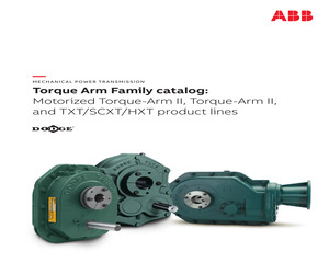
ndling Part Number Index All dimensions are in inches. TO R Q U E - A R M Accessories for TXT5C reducers TXT5C Taper bushed reducers Reducer size Part number AGMA code TXT509CT 245550 TXT515CT 245551 TXT525CT 245552 Weight lbs. Weight lbs. 215D09 8.95 207 TA5M Standard motor mount (143T-286T) 245391 76 215D15 15.40 207 TA5M Special motor mount (324T-326T) 245393 79 215D25 25.56 207 TA5ML Long motor mount (143T-286T) 245392 89 TAB5 Bottom motor mount (143T-326T) 245405 55 TXT5B Backstop assembly 245154 2.2 TXT5D TA reducer belt guard (143T-286T) TXT5C Straight bore reducers Reducer size Part number Actual ratio Part number AGMA code Actual ratio Weight lbs. TXT509CS 245562 215D09 8.95 207 TXT515CS 245563 215D15 15.40 207 TXT525CS 245564 215D25 25.56 207 Description 245387 75 TXT5D TA reducer belt guard for long motor mount (143T-286T) 245102 90 TXT5B Cooling fan assembly 272369 3 TXT5B Taconite auxiliary seal kit 245635 11.9 LUBEKITTXT5 18.5 750000 0.5 TXT5 Lube kit ABB a
 464 Pages, 21793 KB, Original
 Note 1 CnMDATA45m , CnMDATA0m Note 1 , CnMDATA23m Note 1 , CnMDATA3m , Write (8 bits) Note 2 Note 2 (4 x fCPU/fCANMOD + 1)/(2 + j) (MIN.) Note 2 (5 x fCPU/fCANMOD + 1)/(2 + j) (MAX.) Note 2 , Note 1 , Note 1 Write (16 bits) , CnMDATA4m Note 1 Note 1 CnMDATA5M Note 1 , CnMDATA67m CnMDATA6m Note 1 , CnMDATA7m , Note 1 , (2 x fCPU/fCANMOD + 1)/(2 + j) (MIN.) Note (3 x fCPU/fCANMOD + 1)/(2 + j) (MAX.) Note , Read (8/16 bits) (3 x fCPU/fCANMOD + 1)/(2 + j) (MIN.) Note 2 (4 x fCPU/fCANMOD + 1)/(2 + j) (MAX.) Note 2 Note 1 CnMCONFm Note 2 (3 x fCPU/fCAN + 1)/(2 + j) (MIN.) (4 x fCPU/fCAN + 1)/(2 + j) (MAX.) CnMDLCm Note 2 Note 2 CnLOPT CnMCTRLm (3 x fCPU/fCANMOD + 1)/(2 + j) (MIN.) (4 x fCPU/fCANMOD + 1)/(2 + j) (MAX.) Note 1 , Note 1 , Note 1 , CnMIDLm Note 1 CnMIDHm CRC CRCD Write 1 Number of clocks necessary for access = 3 + i + j + (2 + j) x k Notes 1. CAN controller version only 2. Digits below the decimal point are rounded up. Caution Accessing the above registers is prohibited in the following s
 1600 Pages, 9989 KB, Original
3 8 1-3 16 1-2 1-3 CnGMCS, CnGMABT, CnGMABTD, CnMASKaL, CnMASKaH, CnCTRL, CnLEC, CnINFO, CnERC, CnIE, CnINTS, CnBRP, CnBTR, CnTS CnRGPT, CnLIPT, CnTGPT, CnLOPT CnMDATA01m, CnMDATA0m, CnMDATA1m, CnMDATA23m, CnMDATA2m, CnMDATA3m, CnMDATA45m, CnMDATA4m, CnMDATA5M, CnMDATA67m, CnMDATA6m, CnMDATA7m, CnMDLCm, CnMCONFm, CnMIDLm, CnMIDHm, CnMCTRLm = 3ij2jxk CPU CPU i j VSWC40, 1 VSWC40, 1, 2 n, m 1-1 V850ES/FE3, V850ES/FF3, V850ES/FG3, V850ES/FJ3, V850ES/FK3 198 U17793JJ3V1UM 4 4. 1 4 MHz16 MHz 32.768 kHzRC20 kHzR = 390 k, C = 47 pF 240 kHzTYP. 8 MHzTYP. PLL fX = 416 MHzfXX = 416MHz PLLPhase Locked Loop8 fX = 416 MHzfXX = 1248 MHzROM384 KB fX = 416 MHzfXX = 1232 MHzROM256 KB SSCGSpread Spectrum Clock Generator 5 fXTRC 2fRL = 240 kHz, fRH = 8 MHz 7fXX, fXX/2, fXX/4, fXX/8, fXX/16, fXX/32, fXTfRL fXTfRL CLKOUT PCL CSIB0CAN SSCGMAX. fX fXX fRL fRH fXT U17793JJ3V1UM 199 4 4. 1. 1 4-1 OB_7A.STOPXTAL OB_7A.STOPRCZ PCC.FRC XT1 XT2 OB_7B.SUBCLK Xtal 1/2 f XT RC f XT 0 f SC 1 WT, TMM0, TAA1, TAA3, TAA5, TAA7 IDLE
 1092 Pages, 7563 KB, Original
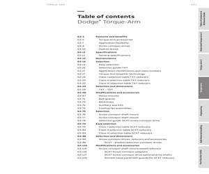
ndling Part Number Index All dimensions are in inches. TO R Q U E - A R M Accessories for TXT5C reducers TXT5C Taper bushed reducers Reducer size Part number AGMA code TXT509CT 245550 TXT515CT 245551 TXT525CT 245552 Weight lbs. Weight lbs. 215D09 8.95 207 TA5M Standard motor mount (143T-286T) 245391 76 215D15 15.40 207 TA5M Special motor mount (324T-326T) 245393 79 215D25 25.56 207 TA5ML Long motor mount (143T-286T) 245392 89 TAB5 Bottom motor mount (143T-326T) 245405 55 TXT5B Backstop assembly 245154 2.2 TXT5D TA reducer belt guard (143T-286T) TXT5C Straight bore reducers Reducer size Part number Actual ratio Part number AGMA code Actual ratio Weight lbs. TXT509CS 245562 215D09 8.95 207 TXT515CS 245563 215D15 15.40 207 TXT525CS 245564 215D25 25.56 207 Description 245387 75 TXT5D TA reducer belt guard for long motor mount (143T-286T) 245102 90 TXT5B Cooling fan assembly 272369 3 TXT5B Taconite auxiliary seal kit 245635 11.9 LUBEKITTXT5 18.5 750000 0.5 TXT5 Lube kit ABB a
 71 Pages, 2911 KB, Original
(MIN.) Note 3 (3 x fXX/fCANMODE + 1)/(2 + j) (MAX.) Read (8/16 bits) (3 x fXX/fCANMODE + 1)/(2 + j) (MIN.) Note 3 (4 x fXX/fCANMODE + 1)/(2 + j) (MAX.) Write 1 CnMDATA01m, CnMDATA0m, CnMDATA1m, CnMDATA23m, CnMDATA2m, CnMDATA3m, CnMDATA45m, CnMDATA4m, CnMDATA5M, CnMDATA67m, CnMDATA6m, CnMDATA7m, CnMDLCm, Note 3 Note Note 3 Note 3 Note 3 Note 3 Note 3 CnMCONFm, CnMIDLm, CnMIDHm CRC CRCD Number of clocks necessary for access = 3 + i + j + (2 + j) x k Notes 1. I2C bus versions (Y products) only 2. CAN controller versions only 3. Digits below the decimal point are rounded up. Caution Accessing the above registers is prohibited in the following statuses. If a wait cycle is generated, it can only be cleared by a reset. * When the CPU operates with the subclock and the main clock oscillation is stopped * When the CPU operates with the internal oscillation clock Remark fXX: Main clock frequency = fXX fCANMOD: CAN module system clock 96 fCAN: Supply clock to CAN i: Values (0 or 1) of higher 4 bits of V
 1195 Pages, 7737 KB, Original
. 741 14.11.33 Message Data Byte 3 Register (MDATA3m) . . . . . . . . . . . . . . . . . . . . . . . . . . 741 14.11.34 Message Data Byte 4 Register (MDATA4m) . . . . . . . . . . . . . . . . . . . . . . . . . . 741 14.11.35 Message Data Byte 5 Register (MDATA5M) . . . . . . . . . . . . . . . . . . . . . . . . . . 742 14.11.36 Message Data Byte 6 Register (MDATA6m) . . . . . . . . . . . . . . . . . . . . . . . . . . 742 14.11.37 Message Data Byte 7 Register (MDATA7m) . . . . . . . . . . . . . . . . . . . . . . . . . . 742 User's Manual U16881EE2V1UM00 13 14.11.38 14.11.39 14.11.40 14.11.41 Message Data Length Code Register (MDLCm) . . . . . . . . . . . . . . . . . . . . . . . 743 Message Configuration Register (MCONFm) . . . . . . . . . . . . . . . . . . . . . . . . . 744 Message Identifier Registers (MIDLm, MIDHm) . . . . . . . . . . . . . . . . . . . . . . . 746 Message Control Register (MCTRLm) . . . . . . . . . . . . . . . . . . . . . . . . . . . . . . 747 Chapter 15 Port Functions . . . . . .
 822 Pages, 3367 KB, Original
fCANMOD + 1) / (2 + j) (MAX.) C0LOPT C0MCTRLm (3 x fXX/fCANMOD + 1) / (2 + j) (MIN.) (5 x fXX/fCANMOD + 1) / (2 + j) (MAX.) Write (16 bits) C0MDATA45m, C0MDATA4m, (2 x fXX/fCANMOD + 1) / (2 + j) (MIN.) Note Note (3 x fXX/fCANMOD + 1) / (2 + j) (MAX.) C0MDATA5M, C0MDATA67m, C0MDATA6m, C0MDATA7m, C0MDLCm, Read (8/16 bits) (3 x fXX/fCANMOD + 1) / (2 + j) (MIN.) Note Note (4 x fXX/fCANMOD + 1) / (2 + j) (MAX.) C0MCONFm, C0MIDLm, C0MIDHm R01UH0290EJ0300 Rev.3.00 Sep 19, 2011 Page 106 of 1817 V850ES/JH3-E, V850ES/JJ3-E CHAPTER 3 CPU FUNCTION Number of clocks necessary for access = 3 + i + j + (2 + j) x k Note Digits below the decimal point are rounded up. Caution Accessing the above registers is prohibited in the following statuses. If a wait cycle is generated, it can only be cleared by a reset. * When the CPU operates with the subclock and the main clock oscillation is stopped * When the CPU operates with the internal oscillation clock Remark i: Values (0) of higher 4 bits of VSWC register j: Values
 1817 Pages, 10111 KB, Original
ster m (CnMDATA23m) CANn message data byte 2 register m (CnMDATA2m) CANn message data byte 3 register m (CnMDATA3m) CANn message data byte 45 register m (CnMDATA45m) CANn message data byte 4 register m (CnMDATA4m) CANn message data byte 5 register m (CnMDATA5M) CANn message data byte 67 register m (CnMDATA67m) CANn message data byte 6 register m (CnMDATA6m) CANn message data byte 7 register m (CnMDATA7m) CANn message data length register m (CnMDLCm) CANn message configuration register m (CnMCONFm) CANn message ID register m (CnMIDLm, CnMIDHm) CANn message control register m (CnMCTRLm) R01UH0129ED0601 Rev. 6.01 User's Manual 725 Chapter 20 CAN Controller (CAN) 20.5.3 CAN registers overview (1) CANn global and module registers The following table lists the address offsets to the CANn register base address CnRBaseAddr. Table 20-19 Address offset CANn global and module registers Register name Symbol R/W CnGMCTRL R/W Access 1-bit 8-bit 16-bit - - After reset 000 H CANn global control register 002 H CA
 1005 Pages, 15838 KB, Original
ster m (CnMDATA23m) CANn message data byte 2 register m (CnMDATA2m) CANn message data byte 3 register m (CnMDATA3m) CANn message data byte 45 register m (CnMDATA45m) CANn message data byte 4 register m (CnMDATA4m) CANn message data byte 5 register m (CnMDATA5M) CANn message data byte 67 register m (CnMDATA67m) CANn message data byte 6 register m (CnMDATA6m) CANn message data byte 7 register m (CnMDATA7m) CANn message data length register m (CnMDLCm) CANn message configuration register m (CnMCONFm) CANn message ID register m (CnMIDLm, CnMIDHm) CANn message control register m (CnMCTRLm) R01UH0128ED0700 Rev. 7.00 User's Manual 457 Chapter 14 CAN Controller (CAN) 14.5.3 CAN registers overview (1) CANn global and module registers The following table lists the address offsets to the CANn register base address: CnRBaseAddr. Table 14-19 Address offset CANn global and module registers Register name Symbol R/W R/W Access After reset 1-bit 8-bit 16-bit - - 0000 H 000 H CANn global control register CnGMCTRL
 1384 Pages, 22773 KB, Original
 N N N N TA4FX TA4FBX TA4FLX TA4FLBX TA4MX TA4MBX TA4MLX TA4MLBX TINI QG CONNECTOR TINI QG,FEMALE PLUG, TINI QG CONNECTOR TINI QG PLUG,FEM,BLK TINI QG CONNECTOR TINI QG PLUG,MALE,BL TINI QG CONNECTOR TINI QG,LARGE STRAIN N N N N N N N TA5FX TA5FLX TA5FLBX TA5MX TA5MBX TA5MLX TA5MLBX TINI QG CONNECTOR TINI QG CONNECTOR TINI QG PLUG,FEM,BLK TINI QG CONNECTOR TINI QG, MALE, BLACK TINI QG CONNECTOR TINI QG PLUG, MALE,B N N TA6FLX TA6MLX TINI QG CONNECTOR TINI QG N N N N TA7FLX TA7MLX TA8FLX TA8MLX TINI QG 7 PIN FEMALE TINI QG 7 PIN MALE P TINI QG CONNECTOR PLASTIC 8 PIN MALE Q S760 S760K S761K S765 S765K S766K TA3FB TA3FL TA3FLB TA3M TA3MB TA3ML TA3MLB TA4F TA4FB TA4FL TA4FLB TA4M TA4MB TA4ML TA4MLB TA5F TA5FL TA5FLB TA5M TA5MB TA5ML TA5MLB TA6FL TA6ML TA7FL TA7ML TA8FL TA8ML TB3M TB3MB TB4M Y Y Y POWER PLUG LOCKING POWER PLUG LOCKING PWR. PLUG,LI POWER PLUG LOCKING POWER PLUG LOCKING PWR.PLUG-LIK EXTENSION JAX
 70 Pages, 286 KB, Original
e Read (3 x fXX/fCAN + 1)/(2 + j) (MIN.) Note (4 x fXX/fCAN + 1)/(2 + j) (MAX.) Note CnMDATA01m, CnMDATA0m, Write (8 bits) Note Write (16 bits) CnMDATA45m, CnMDATA4m, (2 x fXX/fCANMOD + 1)/(2 + j) (MIN.) Note (3 x fXX/fCANMOD + 1)/(2 + j) (MAX.) Note CnMDATA5M, CnMDATA67m, CnMDATA6m, CnMDATA7m, Note (5 x fXX/fCANMOD + 1)/(2 + j) (MAX.) CnMDATA1m, CnMDATA23m, CnMDATA2m, CnMDATA3m, (4 x fXX/fCANMOD + 1)/(2 + j) (MIN.) Read (8/16 bits) (3 x fXX/fCANMOD + 1)/(2 + j) (MIN.) Note (4 x fXX/fCANMOD + 1)/(2 + j) (MAX.) Note CnMDLCm, CnMCONFm, CnMIDLm, CnMIDHm CRC CRCD Write 1 Number of clocks necessary for access = 3 + i + j + (2 + j) x k Note Digits below the decimal point are rounded up. 96 Caution Accessing the above registers is prohibited in the following statuses. If a wait cycle is generated, it can only be cleared by a reset. * When the CPU operates with the subclock and the main clock oscillation is stopped * When the CPU operates with the internal oscillation clock Remark fXX: fCANMOD: fCAN: i:
 1219 Pages, 6475 KB, Original
. 765 14.11.33 Message Data Byte 3 Register (MDATA3m) . . . . . . . . . . . . . . . . . . . . . . . . . . 765 14.11.34 Message Data Byte 4 Register (MDATA4m) . . . . . . . . . . . . . . . . . . . . . . . . . . 765 14.11.35 Message Data Byte 5 Register (MDATA5M) . . . . . . . . . . . . . . . . . . . . . . . . . . 766 14.11.36 Message Data Byte 6 Register (MDATA6m) . . . . . . . . . . . . . . . . . . . . . . . . . . 766 14.11.37 Message Data Byte 7 Register (MDATA7m) . . . . . . . . . . . . . . . . . . . . . . . . . . 766 User's Manual U17411EE1V1UM00 13 14.11.38 14.11.39 14.11.40 14.11.41 Message Data Length Code Register (MDLCm) . . . . . . . . . . . . . . . . . . . . . . . 767 Message Configuration Register (MCONFm) . . . . . . . . . . . . . . . . . . . . . . . . . . 768 Message Identifier Registers (MIDLm, MIDHm) . . . . . . . . . . . . . . . . . . . . . . . . 770 Message Control Register (MCTRLm) . . . . . . . . . . . . . . . . . . . . . . . . . . . . . . . 771 Chapter 15 Port Functions . . .
 850 Pages, 4694 KB, Original
ity level to 5 1 1 0 Sets interrupt priority level to 6 1 1 1 Disables interrupt requests Page 39 Function (Write) 2007-10-10 TMP91FU62 Interrupt Level Setting Registers Symbol Name Address 7 6 5 4 3 2 INTTA5 (TMRA5) INTETA45 INTTA4 & INTTA5 enable ITA5C ITA5M2 INTTA4 (TMRA4) ITA5M1 R ITA5M0 ITA4C R/W ITA4M2 0 0 0 0 0 ITB01C ITB01M2 ITB01M1 R ITB01M0 ITB00C R/W ITB11C 0 0 ITB11M2 0 0 0 ITB11M0 ITB10C R/W ITB10M2 0 ITB10M1 0 R 0 0 ITB10M0 R/W 0 0 ITB21C ITB21M2 0 0 INTTB20(TMRB2) ITB21M1 ITB21M0 ITB20C R R/W ITB20M2 ITB20M1 0 R 0 0 ITB20M0 R/W 0 0 ITB31C ITB31M2 0 0 INTTB30(TMRB3) ITB31M1 ITB31M0 ITB30C ITB30M2 ITB30M1 ITB30M0 9CH R R/W 0 R 0 0 0 INTTBOF1(TMRB1 Over flow) INTETB01V 0 9BH 0 Interrupt enable TMRB0/1 (Over flow) ITB00M0 R/W INTTB31(TMRB3) INTETB3 ITB00M1 INTTB10(TMRB1) ITB11M1 R 0 Interrupt enable TMRB3 ITB00M2 R INTTB21(TMRB2) INTETB2 0 9AH 0 Interrupt enable TMRB2 0 INTTB00(TMRB0) INTTB11(TMRB1) INTETB1 ITA4M0 R/W 99H 0 Interrupt enable TMRB1 ITA4M1 R INTT
 294 Pages, 4269 KB, Original
 R 0 0 R/W 0 0 0 0 I5M1 I5M0 INT5 INTE5 INT5 enable I5C 93H R/W 0 INTTA0 and INTETA01 INTTA1 enable INTTA2 and INTETA23 INTTA3 enable INTTA4 and INTETA45 INTTA5 enable 0 INTTA1 (TMRA1) 95H ITA1C ITA1M2 ITA1M0 ITA0C R/W 0 ITA3M2 0 0 0 ITA3M0 ITA2C ITA5C 0 ITA5M2 0 0 Interrupt request flag 0 0 ITA2M1 ITA2M0 R/W 0 ITA5M0 0 ITA4C R/W 0 ITA0M0 0 0 INTTA4 (TMRA4) ITA5M1 R ITA2M2 R INTTA5 (TMRA5) 97H ITA0M1 R/W 0 R/W 0 0 INTTA2 (TMRA2) ITA3M1 R ITA0M2 R 0 INTTA3 (TMRA3) ITA3C 0 INTTA0 (TMRA0) ITA1M1 R 0 96H I5M2 R ITA4M2 R 0 0 0 ITA4M1 R/W 0 0 lxxM2 lxxM1 lxxM0 0 0 0 Disables interrupt requests 0 0 1 Sets interrupt priority level to 1 0 1 0 Sets interrupt priority level to 2 0 1 1 Sets interrupt priority level to 3 1 0 0 Sets interrupt priority level to 4 1 0 1 Sets interrupt priority level to 5 1 1 0 Sets interrupt priority level to 6 1 1 1 Disables interrupt requests 91C219-36 ITA4M0 0 Function (Write) 2008-02-20 TMP91C219 Symbol Name Address INTETB0 Interrupt enable TMRB0 7
 198 Pages, 1609 KB, Original


