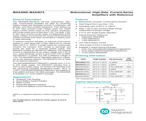
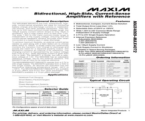
MAX4069-MAX4072 Bidirectional, High-Side, Current-Sense Amplifiers with Reference General Description The MAX4069-MAX4072 low-cost, bidirectional, highside, current-sense amplifiers are ideal for monitoring battery charge and discharge currents in notebooks, cell phones, and other portable equipment. They feature up to 24V input common-mode voltage range, low 100A supply current (which drops to only 10A in shutdown), and a total output error of less than 1.5%. The wide 1.35V to 24V input common-mode range is independent of the supply voltage, ensuring that the current-sense feedback remains accurate even when connected to a battery pack in deep discharge. To achieve maximum flexibility, an external current-sense resistor is used along with a Gain Select pin to choose either 50V/V or 100V/V. A single output pin continuously monitors the transition from charge to discharge and avoids the need for a separate polarity output. The MAX4070 contains an internal 2.5V reference. The charging current is represented by
 15 Pages, 2040 KB, Original
ply Current 10A Supply Current in Shutdown Available in Space-Saving Packages 8-Pin Thin QFN (MAX4070/MAX4071/MAX4072) 8-Pin MAX (MAX4070/MAX4071MAX4072) 10-Pin MAX (MAX4069) Ordering Information PART TEMP RANGE PIN-PACKAGE MAX4069AUB -40C to +125C 10 MAX MAX4070AUA -40C to +125C 8 MAX MAX4070ATA -40C to +125C 8 Thin QFN-EP* MAX4071AUA -40C to +125C 8 MAX MAX4071ATA -40C to +125C 8 Thin QFN-EP* MAX4072AUA -40C to +125C 8 MAX ABN -- ABO -- ABP Typical Operating Circuit Motor Control FROM BATTERY CHARGER Power-Management Systems Cell-Phone Battery-Current Monitoring -- MAX4072ATA -40C to +125C 8 Thin QFN-EP* *EP = Exposed pad. Smart-Battery Packs/Chargers TOP MARK -- RSENSE VBATT = 1.35V TO 24V RS- VCC = 3.6V TO 24V RS+ LOAD VCC MAX4070 GSEL MAX is a registered trademark of Maxim Integrated Products, Inc. Pin Configurations appear at end of data sheet. Functional Diagramsand continued at Guide end of appear data sheet. Pin Configurations Selector at end of UCSP is a trademark of Maxim Integrated Pr
 18 Pages, 1052 KB, Original
 APD Bias Supply Maxim MAX1932ETC USB Microcontroller Microchip PIC16C745-I/SO Low Drop-Out Regulator Maxim MAX1793EUE-33 Inverter Fairchild NC7WZ04P6X Quad ADC Maxim MAX1362EUB High Voltage Current Monitor Maxim MAX4007EUT-T High-Side Current Sense Maxim MAX4070AUA Bi-Directional Level Translator Maxim MAX3373EEKA-T DC-DC Converter Maxim MAX1556ETB Crystal ECS INC. XC679CT HFRD 22.3 PCB MOGPON Evaluation Software Version 1.0 USB A to USB B mini Cable Maxim Integrated Products Page 31 of 36 14 Schematic Figure 6: HFRD 22.3 Schematic, Part 1 - PMD Devices Reference Design HFRD-22.3 (Rev. 4; 03/09) Maxim Integrated Products Page 32 of 36 Schematic (Continued) Figure 7: HFRD 22.3 Schematic, Part 2 - USB Control / Monitoring / Supply Management Reference Design HFRD-22.3 (Rev. 4; 03/09) Maxim Integrated Products Page 33 of 36 15 Board Layout Figure 8: Component Placement Guide Figure 9: Board Layout, Layer 1 Reference Design HFRD-22.3 (Rev. 4; 03/09) Maxim Integrated Products Page 34 of 36 Board Layo
 36 Pages, 1941 KB, Original
 resistor (0402) 681 5% resistor (0402) 0.1 1% resistor (1206) 13 Test points U10 1 U13, U16, U17 3 U14, U19 2 U20, U22 2 U21 1 Y1 1 Microcontroller, Microchip PIC16C745-I/SO Dual inverter, Fairchild NC7WZ04P6X ADC, Max1362EUB High-side current-sense amp, MAX4070AUA Bidirectional level translator, MAX3373EXK Crystal, ECS Inc. XC679CT Maxim Integrated Products Page 10 of 13 9 Schematic Figure 4. HFRD-30.1 SFP+ host board schematic. Reference Design HFRD-30.1 (Rev. 2; 11/08) Maxim Integrated Products Page 11 of 13 10 Board Dimensions/Layout Figure 5. HFRD-30.1 application view, Layer 1. Figure 6. Board layout--component side, Layer 1. Reference Design HFRD-30.1 (Rev. 2; 11/08) Figure 7. Board layout--ground plane, Layer 2. Maxim Integrated Products Page 12 of 13 Figure 8. Board layout--power plane, Layer 3. Figure 9. Board layout--solder side, Layer 4. 11 Layer Profile The HFRD-30.1 SFP+ host board includes controlled-impedance transmission lines (Figure 10). The layer profile is based on the follo
 13 Pages, 854 KB, Original
ply Current 10A Supply Current in Shutdown Available in Space-Saving Packages 8-Pin Thin QFN (MAX4070/MAX4071/MAX4072) 8-Pin MAX (MAX4070/MAX4071MAX4072) 10-Pin MAX (MAX4069) Ordering Information PART TEMP RANGE PIN-PACKAGE MAX4069AUB -40C to +125C 10 MAX MAX4070AUA -40C to +125C 8 MAX MAX4070ATA -40C to +125C 8 Thin QFN-EP* MAX4071AUA -40C to +125C 8 MAX MAX4071ATA -40C to +125C 8 Thin QFN-EP* MAX4072AUA -40C to +125C 8 MAX ABN -- ABO -- ABP Typical Operating Circuit Motor Control FROM BATTERY CHARGER Power-Management Systems Cell-Phone Battery-Current Monitoring -- MAX4072ATA -40C to +125C 8 Thin QFN-EP* *EP = Exposed pad. Smart-Battery Packs/Chargers TOP MARK -- RSENSE VBATT = 1.35V TO 24V RS- VCC = 3.6V TO 24V RS+ LOAD VCC MAX4070 GSEL MAX is a registered trademark of Maxim Integrated Products, Inc. Pin Configurations and Selector Guide appear at end of data sheet. OUT SHDN REFOUT TO ADC 2.5V GND ________________________________________________________________ Maxim Integrated Products For pr
 18 Pages, 379 KB, Original
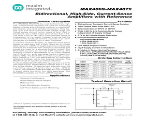
MAX4069-MAX4072 Bidirectional, High-Side, Current-Sense Amplifiers with Reference General Description The MAX4069-MAX4072 low-cost, bidirectional, highside, current-sense amplifiers are ideal for monitoring battery charge and discharge currents in notebooks, cell phones, and other portable equipment. They feature up to 24V input common-mode voltage range, low 100A supply current (which drops to only 10A in shutdown), and a total output error of less than 1.5%. The wide 1.35V to 24V input common-mode range is independent of the supply voltage, ensuring that the current-sense feedback remains accurate even when connected to a battery pack in deep discharge. To achieve maximum flexibility, an external current-sense resistor is used along with a Gain Select pin to choose either 50V/V or 100V/V. A single output pin continuously monitors the transition from charge to discharge and avoids the need for a separate polarity output. The MAX4070 contains an internal 2.5V reference. The charging current is represented by
 14 Pages, 2079 KB, Original
(MAX4071) Low 100A Supply Current 10A Supply Current in Shutdown Available in Space-Saving Packages 8-Pin QFN (MAX4070/MAX4071/MAX4072) 8-Pin MAX (MAX4070/MAX4071MAX4072) 10-Pin MAX (MAX4069) Ordering Information MAX4069AUB -40C to +125C PINPACKAGE 10 MAX MAX4070AUA -40C to +125C 8 MAX MAX4070AGA* -40C to +125C 8 QFN MAX4071AUA -40C to +125C 8 MAX MAX4071AGA* -40C to +125C 8 QFN MAX4072AUA -40C to +125C 8 MAX MAX4072AGA* -40C to +125C 8 QFN PART TEMP RANGE TOP MARK -- -- ABN -- ABO -- ABP *Future product--contact factory for availability. Smart-Battery Packs/Chargers Typical Operating Circuit Motor Control FROM BATTERY CHARGER Power-Management Systems Cell-Phone Battery-Current Monitoring RSENSE VBATT = 1.35V TO 24V Selector Guide PART REFERENCE SUPPLY VOLTAGE RANGE (V) COMMONMODE RANGE (V) MAX4069 ADJUSTABLE 2.7 to 24 1.35 to 24 MAX4070 2.5V 3.6 to 24 1.35 to 24 MAX4071 1.5V 2.7 to 24 1.35 to 24 MAX4072 EXTERNAL 2.7 to 24 1.35 to 24 RS- VCC = 3.6V TO 24V RS+ LOAD VCC MAX4070 GSEL OUT SHDN REFOUT
 16 Pages, 412 KB, Original
ochip PIC16C745-I/SO Digital Temperature Controlled Resistor Maxim DS1859B-050 Inverter Fairchild NC7WZ04P6X Quad ADC Maxim MAX1362EUB Low Drop-Out Regulator Maxim MAX1793EUE-33 High Voltage Current Monitor Maxim MAX4007EUT-T High-Side Current Sense Maxim MAX4070AUA Bi-Directional Level Translator Maxim MAX3373EEKA-T DC-DC Converter Maxim MAX1556ETB Crystal ECS INC. XC679CT HFRD 22.2 PCB MOGPON Evaluation Software Version 1.0 USB A to USB B mini Cable Maxim Integrated Products Page 26 of 31 13 Schematic Figure 6: HFRD-22.2 Schematic, Part 1 -> PMD Devices Reference Design HFRD-22.2 (Rev. 6; 11/08) Maxim Integrated Products Page 27 of 31 Schematic (Continued) Figure 7: HFRD-22.2 Schematic, Part 2 - USB Control / Monitoring / Supply Management Reference Design HFRD-22.2 (Rev. 6; 11/08) Maxim Integrated Products Page 28 of 31 14 Board Layout Figure 8: Board Layout / Dimensions / Component Placement Guide Figure 9: Board Layout, Layer 1 Reference Design HFRD-22.2 (Rev. 6; 11/08) Maxim Integrated Prod
 31 Pages, 1799 KB, Original
0F 10% CERAMIC CAPACITOR (0805) 3 C21 C23 C37 4.7F 10% CERAMIC CAPACITOR (0805) 4 C1 C3-5 22F 10% TANTALUM CAPACITOR 1206 3 L2-4 4.7H 1 D2 2 U14 U19 1 U21 2 4 Coilcraft Power Inductor DS1608-472MLB GREEN LED MAX1362EUB MAX3373EEKA-T U20 U22 Do Not Install MAX4070AUA R89 R94 R97 R98 0 RESISTOR (0402) R93 R90 0 RESISTOR (0402) 1 R24 1.5k 1% RESISTOR (0402) 12 R3-5 R7 R9-10 R25 R49-51 R92 R107 10k 1% RESISTOR (0402) 2 R87-88 24.9k 1% RESISTOR (0402) 7 R11-14 R52 R55 R86 49.9 1% RESISTOR (0402) 1 R91 680 1% RESISTOR (0402) 2 R1-2 0.025 1% RESISTOR (1206) 0.125W 2 16 J5-20 2 TP13-14 SMA SIDE MOUNT TAB CONTACT JOHNSON 142-0701-851 TESTPOINT DIGI-KEY 5000K-ND Digi-Key is a registered trademark of Digi-Key Corporation. Reference Design HFRD-32.0 (Rev. 2; 11/08) Maxim Integrated Products Page 24 of 24
 24 Pages, 2178 KB, Original
71) Low 100A Supply Current 10A Supply Current in Shutdown Available in Space-Saving Packages 8-Pin Thin QFN (MAX4070/MAX4071/MAX4072) 8-Pin MAX (MAX4070/MAX4071MAX4072) 10-Pin MAX (MAX4069) Ordering Information MAX4069AUB -40C to +125C 10 MAX TOP MARK -- MAX4070AUA -40C to +125C 8 MAX -- PART TEMP RANGE PIN-PACKAGE MAX4070ATA -40C to +125C 8 Thin QFN-EP* MAX4071AUA -40C to +125C 8 MAX MAX4071ATA -40C to +125C 8 Thin QFN-EP* MAX4072AUA -40C to +125C 8 MAX MAX4072ATA -40C to +125C 8 Thin QFN-EP* ABN -- ABO -- ABP *EP = Exposed paddle. Smart-Battery Packs/Chargers Typical Operating Circuit Motor Control FROM BATTERY CHARGER Power-Management Systems Cell-Phone Battery-Current Monitoring RSENSE VBATT = 1.35V TO 24V Selector Guide PART REFERENCE SUPPLY VOLTAGE RANGE (V) COMMONMODE RANGE (V) MAX4069 ADJUSTABLE 2.7 to 24 1.35 to 24 MAX4070 2.5V 3.6 to 24 1.35 to 24 MAX4071 1.5V 2.7 to 24 1.35 to 24 MAX4072 EXTERNAL 2.7 to 24 1.35 to 24 RS- VCC = 3.6V TO 24V RS+ LOAD VCC MAX4070 GSEL OUT SHDN REFOUT TO A
 16 Pages, 363 KB, Original
2 Y1 1 SPDT Analog Switch, MAX4729EXT-T Digital Resistor DS3902U-530 Microcontroller, Microchip PIC16C745-I/SO Dual Inverter, Fairchild NC7WZ04P6X LDO Regulator, MAX1793EUE-33 Dual Buffer, Fairchild NC7WZ16P6X ADC, Max1362EUB High-Side Current-Sense Amp., MAX4070AUA Bidirectional Level Translator, MAX3370EXK Crystal, ECS Inc. XC679CT Maxim Integrated Products Page 12 of 15 9 Schematic Figure 6. HFRD-26.0 SFF GEPON host board schematic. Reference Design HFRD-26.0 (Rev. 8; 11/08) Maxim Integrated Products Page 13 of 15 10 Board Dimensions/Layout Figure 7. HFRD-26.0 application view, Layer 4. Figure 8. Board layout--component side, Layer 1. Reference Design HFRD-26.0 (Rev. 8; 11/08) Figure 9. Board layout--ground plane, Layer 2. Maxim Integrated Products Page 14 of 15 Figure 10. Board layout--power plane, Layer 3. Figure 11. Board layout--solder side, Layer 4. 11 Layer Profile The HFRD-26.0 GEPON SFF host board includes controlled-impedance transmission lines. The layer profile is based on the follo
 15 Pages, 1063 KB, Original


